Showing posts with label mikrotik. Show all posts

TIP: Protect Your Router Against IP Spoofing

I was reading through some of the best practice configuration of Mikrotik routers, and routers in general. I found a very helpful tip about helping keep the internet secure for others. And this is related to the topic stated in the title -- IP Spoofing. In order to gain more information regarding this terminology, here's a resource that defined it clearly. Also quoted the same definition below.
IP Spoofing is a technique used to gain unauthorized access to machines, whereby an attacker illicitly impersonate another machine by manipulating IP packets. IP Spoofing involves modifying the packet header with a forged (spoofed) source IP address, a checksum, and the order value.

As a responsible infrastructure administrator, I am obliged to contribute to the security of others. And with that, likewise share the same information on how to do it as well for others benefit. If you own a Mikrotik router, follow the procedure below.

RP Filter. The "RP Filter" is used for packet source validation. As defined in RFC3704 Abstract, it is designed to limit the impact of distributed denial of service attacks, by denying traffic with spoofed addresses access to the network, and to help ensure that traffic is traceable to its correct source network.

To be better informed about this change, here's a link to the Mikrotik Wiki.

So how is this done in the Mikrotik?

To those who want to do it via command line interface (CLI), execute this using a privileged account:
/ip settings
set rp-filter=strict

Those who would rather use WinBox utility, IP » Settings. Set "RP Filter" to "strict".
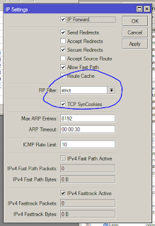
Winbox IP Settings

In the screenshot above, "TCP SynCookies" is ticked. This is a further router protection from DDoS via SYN floods. For the CLI equivalent to that, the CLI command above should be changed to:
/ip settings
set rp-filter=strict tcp-syncookies=yes

 RELATED: Mikrotik Articles in This Series

The above changes did not increase the resource consumption on my router. Monitor your router for changes to utilization of resources to see if the change does introduce significant load.

Share:

HOW-TO: Mangle (or QoS) in a Mikrotik Router

First of all, let me tell you that I'm in no way a Mikrotik expert. My expertise is system administration, more into servers and storage. My specialization in the later years of infrastructure work focused primarily on VMware virtualization. I just understand a few concepts of networking that allow me to be comfortable around the equipment and possibly playing with it. There are occassions where necessity calls for that ease around hardware and these are one of those.

Previous articles have discussed the configuration on a Mikrotik Router as I have experienced it -- the initial configuration and succeeding LAN provisions, like DHCP and DNS. I have had this configuration working for me and had tested it to work.

The concept of QoS in this article is "Q-on-Q" in the Mikrotik linggo. There are a lot of ways to configure this and mine is not the only way. I have not tested the other configurations out there. This is the first one I have tested as this seems to be the easiest to implement and test (at least in my point of view).

There are two (2) components to this -- a queue tree and sets of mangle rules.

Queue Tree. The best analogy I could come up with for the concept of queue trees is the highway. Have a separate lane for faster and higher priority vehicles and leave the rest for vehicles that require roads to get through. The difference is QoS only kicks in when congestion happens. And in order for the configuration to kick in, at about 90% bandwidth utilization, I create an artificial congestion for this configuration to start to take control in anticipation of the real world actual congestion.

I was given an internet bandwidth of 20MBps up and 20MBps down to play with. Following the concept above, I created two (2) queues -- one queue for critical traffic with a CIR of 3MBps and another for best effort queue with a CIR of 15MBps. In effect, the artificial congestion at 90% utilization of 18MBps aggregated at the parent queue. QoS settings take over when bandwidth utilization for those queues are saturated as well as on their parent queues. The committed information rate or CIR (limit-at value) for that specific queue assures it that bandwidth, if required. Bandwidth for a particular queue that is unused can be "borrowed" by other queues.

I mirrored the same configs for both upload queues and download queues since my bandwidth is symmetrical. The queue tree configuration follows below.
/queue tree
add comment="----- uploads -----" max-limit=25M name=UPLDQ parent=global \
 priority=1 queue=ethernet-default
add comment="----- low priority -----" limit-at=15M max-limit=25M name=\
 UPLD_BEFF parent=UPLDQ priority=5 queue=ethernet-default
add comment="---- high priority -----" limit-at=3M max-limit=25M name=\
 UPLD_CRIT parent=UPLDQ priority=1 queue=ethernet-default
add name=upld_pr1_crit packet-mark=upld_pr1_crit parent=UPLD_CRIT \
 priority=1 queue=ethernet-default
add name=upld_pr2_crit packet-mark=upld_pr2_crit parent=UPLD_CRIT \
 priority=2 queue=ethernet-default
add name=upld_pr7_crit packet-mark=upld_pr7_crit parent=UPLD_CRIT \
 priority=7 queue=ethernet-default
add name=upld_pr1_beff packet-mark=upld_pr1_beff parent=UPLD_BEFF \
 priority=1 queue=ethernet-default
add name=upld_pr2_beff packet-mark=upld_pr2_beff parent=UPLD_BEFF \
 priority=2 queue=ethernet-default
add name=upld_pr4_beff packet-mark=upld_pr4_beff parent=UPLD_BEFF \
 priority=4 queue=ethernet-default
add name=upld_pr6_beff packet-mark=upld_pr6_beff parent=UPLD_BEFF \
 priority=6 queue=ethernet-default
add name=upld_pr7_beff packet-mark=upld_pr7_beff parent=UPLD_BEFF \
 priority=7 queue=ethernet-default
add name=upld_pr8_beff packet-mark=upld_pr8_beff parent=UPLD_BEFF \
 queue=ethernet-default
add max-limit=6M name=upl_pr8_ratelimited packet-mark=upld_pr8_lmtd \
 parent=UPLD_BEFF queue=ethernet-default
add comment="----- downloads -----" max-limit=25M name=DNLDQ \
 parent=global priority=1 queue=ethernet-default
add comment="----- low priority ----" limit-at=15M max-limit=25M \
 name=DNLD_BEFF parent=DNLDQ priority=5 queue=ethernet-default
add comment="---- high priority ----" limit-at=3M max-limit=25M \
 name=DNLD_CRIT parent=DNLDQ priority=1 queue=ethernet-default
add name=dnld_pr1_crit packet-mark=dnld_pr1_crit parent=DNLD_CRIT 
 priority=1 queue=ethernet-default
add name=dnld_pr2_crit packet-mark=dnld_pr2_crit parent=DNLD_CRIT \
 priority=2 queue=ethernet-default
add name=dnld_pr7_crit packet-mark=dnld_pr7_crit parent=DNLD_CRIT \
 priority=7 queue=ethernet-default
add name=dnld_pr1_beff packet-mark=dnld_pr1_beff parent=DNLD_BEFF \
 priority=1 queue=ethernet-default
add name=dnld_pr2_beff packet-mark=dnld_pr2_beff parent=DNLD_BEFF \
 priority=2 queue=ethernet-default
add name=dnld_pr4_beff packet-mark=dnld_pr4_beff parent=DNLD_BEFF \
 priority=4 queue=ethernet-default
add name=dnld_pr6_beff packet-mark=dnld_pr6_beff parent=DNLD_BEFF \
 priority=6 queue=ethernet-default
add name=dnld_pr7_beff packet-mark=dnld_pr7_beff parent=DNLD_BEFF \
 priority=7 queue=ethernet-default
add name=dnld_pr8_beff packet-mark=dnld_pr8_beff parent=DNLD_BEFF \
 queue=ethernet-default
add max-limit=6M name=dnld_pr8_lmtd packet-mark=dnld_pr8_lmtd \
 parent=DNLD_BEFF queue=ethernet-default

As seen from above, I adopted a naming convention for the queues (and their corresponding packet-marks). Packet-marks take the name of the queue names; whereas queue names have a specific naming concatenated from their function (dnld for download; upld for upload), priority (pr1 for priority 1 and so on..) and parent queue (beff for best effort; crit for critical or high priority queue). It helps me identify the queue assignment when classifying packets based on the kind of traffic they belong to).

Mangle Rules. Now that the queues are made, let's classify traffic by marking the packets. These packet marks or tags identify them as to which particular queue they would go to. Do you see now how these two components go hand in hand?

Note that these packet marks are only applicable within the Mikrotik router. The order of the rules are based on traffic volume. This gives me efficiency as the rules are evaluated from top to bottom. When the top rules are hit first, rules further down need no execution. The procedure below moves everything to Priority 4, and other packets are reclassified to lower or higher priority from that baseline. By default all packets have Priority 8. Below are the mangle rules I use.
/ip firewall mangle
add action=mark-connection chain=prerouting comment=">>>>> INTRANET TRAFFIC" \
 disabled=yes new-connection-mark=no-mark
add action=jump chain=forward dst-address=10.0.0.0/8 jump-target=local-net \
 src-address=10.0.0.0/8
add action=mark-connection chain=local-net new-connection-mark=local-net \
 passthrough=yes
add action=fasttrack-connection chain=local-net connection-mark=local-net
add action=accept chain=local-net connection-mark=local-net
add action=return chain=local-net
add action=accept chain=prerouting comment=">>>>> SEPARATOR (DO NOT ENABLE)" \
 disabled=yes
add action=mark-packet chain=prerouting in-interface=all-ethernet \
 new-packet-mark=dnld_pr4_beff
add action=mark-packet chain=postrouting new-packet-mark=upld_pr4_beff \
 out-interface=all-ethernet
add action=accept chain=prerouting comment=">>>>> SEPARATOR (DO NOT ENABLE)" \
 disabled=yes
add action=jump chain=prerouting comment="NEW CONNECTIONS" connection-state=\
 new in-interface=all-ethernet jump-target=crit-dnld-pr1
add action=jump chain=postrouting connection-state=new jump-target=\
 crit-upld-pr1 out-interface=all-ethernet
add action=jump chain=prerouting jump-target=crit-dnld-pr1 port=53 protocol=udp
add action=jump chain=prerouting comment="BIG BYTES (IN)" connection-bytes=\
 2500000-0 connection-rate=2500-1G in-interface=ether1 jump-target=\
 beff-bulk-download protocol=tcp
add action=mark-packet chain=beff-bulk-download new-packet-mark=\
 dnld_pr8_beff passthrough=no
add action=return chain=beff-bulk-download
add action=jump chain=postrouting comment="BIG BYTES (OUT)" connection-bytes=\
     2500000-0 connection-rate=2500-1G jump-target=beff-bulk-upload \
 out-interface=ether1 protocol=tcp
add action=mark-packet chain=beff-bulk-upload new-packet-mark=\
 upld_pr8_beff passthrough=no
add action=return chain=beff-bulk-upload
add action=jump chain=prerouting comment="WEB TRAFFIC - INBOUND" \
 in-interface=ether1 jump-target=beff-http-down port=80,443 protocol=tcp
add action=jump chain=prerouting in-interface=ether1 jump-target=\
 beff-http-down port=80,443 protocol=udp
add action=jump chain=beff-http-down connection-bytes=2500000-0 \
 jump-target=beff-bulk-download protocol=tcp
add action=mark-packet chain=beff-http-down new-packet-mark=\
 dnld_pr6_beff passthrough=no
add action=return chain=beff-http-down
add action=jump chain=prerouting comment="SYN PACKETS" in-interface=ether1 \
 jump-target=crit-dnld-pr2 protocol=tcp tcp-flags=syn
add action=jump chain=postrouting jump-target=crit-upld-pr2 out-interface=\
 ether1 protocol=tcp tcp-flags=syn
add action=jump chain=forward comment="PR1 - RTP conn/packet" \
 jump-target=crit-dnld-pr1 port=10000-20000 protocol=udp
add action=jump chain=forward comment="PR1 -- FACETIME" jump-target=\
 crit-dnld-pr2 port=5223,4080,3478 protocol=tcp
add action=mark-connection chain=forward comment="DSCP 46 (VoIP)" \
 connection-mark=no-mark dscp=46 new-connection-mark=VoIP-conn \
 passthrough=yes
add action=jump chain=prerouting comment="PR2 -- SIP (VoIP)" jump-target=\
 crit-dnld-pr1 port=5060-5061 protocol=tcp
add action=jump chain=prerouting jump-target=crit-dnld-pr1 port=5060-5061 \
 protocol=udp
add action=jump chain=forward comment="PR8 -- P2P conn/packet" jump-target=\
 beff-p2p p2p=all-p2p src-address=10.0.0.0/8
add action=mark-packet chain=beff-p2p new-packet-mark=dnld_pr8_lmtd \
 passthrough=no
add action=return chain=beff-p2p
add action=accept chain=prerouting comment=">>>>> SEPARATOR (DO NOT ENABLE)" \
 disabled=yes
add action=mark-packet chain=crit-dnld-pr1 new-packet-mark=dnld_pr1_crit \
 passthrough=no
add action=return chain=crit-dnld-pr1
add action=mark-packet chain=crit-dnld-pr2 new-packet-mark=dnld_pr2_crit \
 passthrough=no
add action=return chain=crit-dnld-pr2
add action=mark-packet chain=crit-upld-pr1 new-packet-mark=upld_pr1_crit \
 passthrough=no
add action=return chain=crit-upld-pr1
add action=mark-packet chain=crit-upld-pr2 new-packet-mark=upld_pr2_crit \
 passthrough=no
add action=return chain=crit-upld-pr2

With the configuration above, packets are re-classified according to traffic type. Even if someone is browsing the web and somebody else is uploading files through popular cloud storage like Dropbox or Google Drive, VoIP calls are still as clear as they need to be. My internal customers are satisfied with the speed of their internet and cloud experience.

 RELATED: LAN Configuration of a Mikrotik Virtual Router

If you find something amiss in my configuration or if you found a way to improve it, I would appreciate some feedback. Hope this helps.

Share:

HOW-TO: NAT (Network Address Translation) on a Mikrotik Router

Previous articles have discussed the configuration on a Mikrotik Router as I have experienced it -- the initial configuration and succeeding LAN provisions, like DHCP and DNS. I have linked those to the corresponding posts, should you want to check them out. This time, let's outline the internet access side of the configurations.

It is likely that your internet service provider (ISP) will not give you an entire block of IP addresses (otherwise, it will be a very expensive service). They expect you configure some form of network address translation in order to access the internet or traverse to another network. In order to understand the concepts, let us define the two common methods of NAT, which are source NAT (in Mikrotik lingo "srcnat") and destination NAT (in Mikrotik lingo "dstnat"). Just keep in mind that for connections bound to the internet (going out of the network), srcnat is involved; consequently, for connections going in to the local area network, it is dstnat.

NAT in this case does the one-to-many translations. As the traffic passes through the router bound for the internet, the router "masquerades" the IP address of the packet with the public IP address (refer to the initial configuration post) of the router (as additional reading references, you may want to checkout the RFC1918 standard). The router also performs another significant function of tracking the active connections. When inbound packets return, it uses this tracking information to determine the private IP address to forward the packets to.

Having mentioned that, there are two major configuration blocks that need to be added to the Mikrotik router. The NAT part and the firewall forward chain part. At your discretion, you may also want to adjust connection tracking parameters of the router, if the default configuration does not fit.

LAN-to-ISP Network Topology

SRCNAT. First, source NAT or srcnat. Still taking into account the same configuration that we used in the previous articles. Given a static public IP address, srcnat is best deployed.
/ip firewall nat
add action=srcnat chain=srcnat out-interface=ether1 \
 src-address=192.168.1.0/24 to-addresses=1.1.1.2

Another way of configuring this is to use another form of source NAT called "masquerade". Masquerade is a specialized form of srcnat. While srcnat requires a destination IP address, masquerade requires a specific interface and retrieves the IP address assigned to the interface when performing the NAT process. There is an associated overhead to masquerade due to this. Just know that in the absence of a static public IP, masquerade is the solution to go. Masquerade was created to work with dynamic IP addresses on the outbound interfaces.
/ip firewall nat
add action=masquerade chain=srcnat out-interface=ether1 \
 src-address=192.168.1.0/24

Given a static public IP address on the outbound interface, both configurations will work. However, it is recommended to use the first configuration to minimize overhead. I have not tested how big the overhead is on my setup but I guess it will vary from setup to setup.

FORWARD chain. The router's built-in firewall needs to be instructed to forward packets NAT'd to the local area network. It needs to accept new connections initiated from the LAN as well.

/ip firewall filter
add chain=forward action=drop comment="DROP invalid packets" connection-state=invalid
add chain=forward action=accept comment="FORWARD packets from LAN" \
 connection-state=related,established

This block of code needs to come after the input chain (router protection).

 RELATED: Initial Configuration of a Mikrotik Virtual Router

There you go, after putting the above code in conjuction with the previous configurations done, you will now have a working router able to provide basic network connectivity plus internet access. Next we will discuss quality of service (QoS) or packet prioritization and bandwidth shaping on the Mikrotik router.

Share:

HOW-TO: LAN Configuration of a Mikrotik Virtual Router

In the previous article, we discussed about the configuration of the Mikrotik router, with particular focus on connectivity and protection from unauthorized access. This time, we could start with specific services that it will provide to the local area network (LAN).

Configuring on the LAN side, requires that we prevent locking ourselves out of the router while executing changes. What does this mean? Any change that will potentially disconnect us from the router will be blocked. The router is smart enough to figure this out. In the Mikrotik linggo, the term used to refer to this is "safe mode". The name itself is very intuitive!

To enable safe mode, simultaneously press [CTRL]+[X] on the keyboard. The same set of hotkeys used for "cut" to those familiar with the Windows world. Upon enabling safe mode, the terminal prompt changes with the string ‹SAFE› appended to it. You will see that in the screenshot below.

Mikrotik SSH Safe Mode

To release safe mode, the same set of keys are used. Similarly, the prompt returns to normal and it shows that safe mode is no longer in effect.

Mikrotik SSH Safe Mode (Toggle)

Without further ado, let us configure the router to be able to perform DNS lookups for our network. This configuration forwards queries to Google's public DNS servers (8.8.8.8 and 8.8.4.4) at the same time caches the queries in the router's memory. Change the DNS servers to your own if Google's DNS servers are not desired.
/ip dns
set allow-remote-requests=yes cache-size=4098KiB servers=8.8.4.4,8.8.8.8

Next, let us prepare the network segments used on the LAN side by defining an IP pool. This will be used for DHCP services later. Let us assume a segment from 192.168.1.0/24.
/ip pool
add name=POOL1 ranges=192.168.1.11-192.168.1.239

Once the pool is defined, let's use that pool for DHCP services. This is done in two-parts. First, define the network segment.
/ip dhcp-server network
add address=192.168.1.0/24 comment=LOCAL_LAN dns-server=192.168.1.1 \
 domain=pimp-my-rig.local gateway=192.168.1.1 \
 ntp-server=NTP_SVR_IP_HERE wins-server=WINS_SVR_IP_HERE

Second, define the DHCP directive.
/ip dhcp-server
add add-arp=yes address-pool=POOL1 authoritative=yes disabled=no \
 interface=ether3 lease-time=1d name=DHCP1

This configuration will not be complete without assigning the LAN gateway IP address to an existing interface on the router. In this case, it is ether3.
/ip address
add address=192.168.1.1/24 comment=LOCAL_LAN interface=ether3 network=192.168.1.0

At this point, the router is able to provide communication between the devices in the local area network. It will be able to support devices that require dynamic host configuration protocol (or DHCP) for automatic configuration of IP addresses. Internet connectivity could not be established since the RFC1918 addresses (to which the 192.168.0.0/16 network belongs) are non-routable on the internet. What needs to happen is network address translation (or NAT). And the Mikrotik router is just as able to perform this task. We will discuss that in the next article.

 RELATED: Initial Configuration of a Mikrotik Virtual Router

For now the router is able to provide network connectivity to hosts within the LAN. It could provide DHCP addresses and cache DNS queries. Please note that all capitalized configuration keywords (e.g. POOL1, DHCP1 and LOCAL_LAN) can be replaced with your own naming convention(s).

Share:

HOW-TO: Initial Configuration of a Mikrotik Virtual Router

This year, I shifted technology specialization away from the infrastructure profession to data science, with more particular focus on data cleansing, mining, and archiving and warehousing. And necessities sometimes require application of my infrastructure background and experience. This is what I like about my new assignment -- never a boring day. Had the chance to work on selection of virtual routers, to which I ended up shortlisting two of them, namely, VyOS and Mikrotik.

Eventually, the pick ended up Mikrotik. And will be posting several notes on my adventure with Mikrotik Virtual Router. For all intents and purposes, this post pertains to VMware setup on x86 architecture. For now let us cover the initial setup.

After downloading the ISO from the Mikrotik website (obtain a license as well), prepare the virtual machine. On mine, I set it up with 2 vCPUs, 512MB of memory and 1GB of disk space. Remove other hardware from the initial configuration (e.g. Floppy Drive, USB ports, etc) that a network router will not have. The setup is pretty straight forward, so let's skip that part and assume it went well.

While on the Mikrotik website, download their utility application called "winbox". This will come in very handy to configure the router.

Other tutorials suggest to rename the network interfaces to WAN and LAN; others, ether1-gateway and ether2-local. On mine, I left them as is. So you don't get confused on my setup, ether1 is facing the ISP (my primary WAN link), ether2 is facing the backup WAN, and ether3 is facing my local area network. Please note that all my network interfaces use the vmxnet3 virtual network cards. You may add as many NICs as you need, but for me this is enough for my requirement.

Your ISP will probably give you both a /30 and /29 IP block. You will need that information. I cannot provide the particulars of my address blocks so for all intents and purposes, let us assume that to be 1.1.1.1/30. To make things easier to interpret, you may plug that information in an IP calculator to obtain more details that need to be added to the router configuration.

IPCALC IP Calculator

Assign that /30 IP address on the Mikrotik router. This is could be done a couple of ways.. First the winbox (GUI) way, IP » Addresses and put the IP address information and set it on interface ether1. Via CLI (terminal on winbox, or telnet, or SSH), /ip address add address=1.1.1.2/30 network=1.1.1.0 comment=WAN-PRI interface=ether1. The router will be reachable at its default address of 192.168.88.1/24 (username is "admin" without a password). Note that 1.1.1.2/30 (address) and 1.1.1.0 (network) were taken from the IP calculator, as seen above.

Next, secure and protect the router from external access by putting a password, turning off unnecessary services and putting firewall rules.

For my setup, I provided a password for admin then limited its access to the console. I created another password-protected username with full admin access but unlike admin its limits allow access from the LAN.
/user set admin password=PASSWORD address=127.0.0.1/32
/user add name=pimp-my-rig password=PASSWORD group=full address=192.168.0.0/16

After setting the admin password, you may choose to disable it. And use another administrative account in its place. Simply append the string "disabled=yes" to the line containing admin. This makes it harder for external hacks to your router especially since it is the router facing your ISP.

Unwanted Services. Access to the router is open by default. It needs lockdown to be secure. I also disabled services that I no longer need. You will see those below with the "disabled=yes" string appended.
/ip service
set telnet address=192.168.0.0/16 disabled=yes
set ftp address=192.168.0.0/16 disabled=yes
set www address=192.168.0.0/16 disabled=yes
set ssh address=192.168.0.0/16
set www-ssl address=192.168.0.0/16 disabled=yes
set api address=192.168.0.0/16 disabled=yes
set winbox address=192.168.0.0/16
set api-ssl address=192.168.0.0/16 disabled=yes

Execute a "print" to check the current configuration. You should see something similar.

Mikrotik Router Default Services

Firewall. Extend the protection to the built-in firewall. The rules I used are below.
/ip firewall filter
add chain=input action=tarpit protocol=tcp in-interface=!ether3 \
 comment="TARPIT connections not coming from LAN (ETH3)"
add chain=input action=drop in-interface=!ether3 \
 comment="DROP other traffic not comming from LAN (ETH3)"

Execute a "print" to check the current configuration. You should see something similar.

Mikrotik Router Initial Firewall

Rules are interpreted from top to bottom and the lesser rules there are the faster the router performs. Not to mention lesser resources are consumed. This should be pretty much lockdown the router while it allows configurations and customizations from the console or terminal sessions from the LAN interface. I will post configuration on the LAN side and services like DNS, DHCP, web-proxy and NTP in succeeding articles.

You may also opt to drop external traffic rather than tarpit. For more information regarding the action tarpit, refer to this excellent explanation from Wikipedia.

 RELATED: Install Adblock on Raspberry Pi via Pi-Hole

I am a CLI guy so I did my configuration mostly on the command line. Hope this helps you in getting your router up and running.

Share:

Subscribe for Latest Update

Popular Posts

Post Labels

100gb (1) acceleration (1) acrobat (1) adblock (1) advanced (1) ahci (1) airdrop (2) aix (14) angry birds (1) article (21) aster (1) audiodg.exe (1) automatic (2) autorun.inf (1) bartpe (1) battery (2) bigboss (1) binance (1) biometrics (1) bitcoin (3) blackberry (1) book (1) boot-repair (2) calendar (1) ccleaner (3) chrome (5) cloud (1) cluster (1) compatibility (3) CPAN (1) crypto (3) cydia (1) data (3) ddos (1) disable (1) discount (1) DLNA (1) dmidecode (1) dns (7) dracut (1) driver (1) error (10) esxi5 (2) excel (1) facebook (1) faq (36) faucet (1) firefox (17) firewall (2) flash (5) free (3) fun (1) gadgets (4) games (1) garmin (5) gmail (3) google (4) google+ (2) gps (5) grub (2) guide (1) hardware (6) how (1) how-to (45) huawei (1) icloud (1) info (4) iphone (7) IPMP (2) IPV6 (1) iscsi (1) jailbreak (1) java (3) kodi (1) linux (28) locate (1) lshw (1) luci (1) mafia wars (1) malware (1) mapsource (1) memory (2) mikrotik (5) missing (1) mods (10) mouse (1) multipath (1) multitasking (1) NAT (1) netapp (1) nouveau (1) nvidia (1) osmc (1) outlook (2) p2v (2) patch (1) performance (19) perl (1) philippines (1) php (1) pimp-my-rig (9) pldthomedsl (1) plugin (1) popcorn hour (10) power shell (1) process (1) proxy (2) pyspark (1) python (13) qos (1) raspberry pi (7) readyboost (2) reboot (2) recall (1) recovery mode (1) registry (2) rename (1) repository (1) rescue mode (1) review (15) right-click (1) RSS (2) s3cmd (1) salary (1) sanity check (1) security (15) sendmail (1) sickgear (3) software (10) solaris (17) squid (3) SSD (3) SSH (9) swap (1) tip (4) tips (42) top list (3) torrent (5) transmission (1) treewalk (2) tunnel (1) tweak (4) tweaks (41) ubuntu (4) udemy (6) unknown device (1) updates (12) upgrade (1) usb (12) utf8 (1) utility (2) V2V (1) virtual machine (4) VirtualBox (1) vmware (14) vsphere (1) wannacry (1) wifi (4) windows (54) winpe (2) xymon (1) yum (1) zombie (1)

RANDOM POSTS